270799 Posts in 19739 Topics - by 1829 Members - Latest Member: Simplesimon

Hello Guest
Show unread posts since last visit.
Show new replies to your posts.

Author Topic: DIY: Transmission work NV5600  (Read 11565 times)

Offline R0oster31

  • Tech Certified
  • Master Technician
  • *****
  • Posts: 1514
  • Awards:
    DonorROTMTech Certified500HPAF
DIY: Transmission work NV5600
« on: April 09, 2009, 02:25:45 pm »
Doing transmission work on an NV 5600 is no simple task and I am no expert, but will do my best to describe the work that I performed.  The first step is to get the transmission out of the truck.  I have a 4X4 so if you have a 2 wheel drive model it will be a little easier.  As always safety is the most important thing, so first thing is to disconnect the negative terminals of the batteries (you will be removing the starter and don’t want anything to turn over should you bump something). First you have to remove everything that is connected to, or will get in the way of the transmission.  These things include, shift tower, starter, clutch release cylinder, reverse sensor wires, driveshafts (front and rear), transfer case linkage, vacuum lines, and suspension cross member.  I recommend using plastic bags for nuts and bolts to keep them separate and make it easy to put back together.
I most of the stuff is metric, but I used both metric and standard sizes, just using which ever one fit tighter.  I also recommend 6 point whenever you can use it.  To remove the shift tower you will probably have to remove your center console.  To do this you will have to remove a couple screws.  You will have to remove the boots on the two shift sticks.  The transfer case shifter just snaps into place and the main stick boot bolts into place.  If you lift the bottom wrinkle, you will be able to see those bolts.
 
I removed the transfer case shifter (10 mm) to make it easier to get the console out.  Once you have those two unbolted you will be able to lift them up to find the bolts that hold the center console in.  There are also two bolts underneath the rubber in the cup holders.  A small screw driver works well to help pull the rubber out.

 
Once you have the center counsel out you can remove the lower dust boot and then take out the 4 bolts to remove the shift tower.

 
The clutch release cylinder is removed by taking out two bolts and just pulling straight out. It is located on the driver’s side.

To remove the starter there are three bolts.  The bolts look a little strange but a 10mm 12 point wrench or socket will take them out just fine.  The top one is hard to reach but if you feel around you can find it and get a wrench on there. It is located on the driver’s side.

To disconnect the reverse sensor you just pull the connector out.  It is located on the passenger side.

To disconnect the vacuum lines push them off, if you try and pull them off the lines will constrict.  I disconnected the two hard lines from the frame rail and support cross member to make sure I didn’t bend them.  In order to make sure I didn’t mix them up I just put a piece of tape around one on them on each end and on the corresponding hoses. Driver’s side.


  There are also a couple connections on top of the transfer case.  One is a connector that has a couple hoses and one is a single hose, just push these off as well.  Top of transfer case driver’s side.

To disconnect the transfer case linkage there is a pin in the end closest to the transfer case that is removed by taking out the key.  I removed the pin and then wired up the linkage so I wouldn’t have to completely remove it. Driver’s side.

To remove the rear driveshaft you will take apart the U-joint.  The driveshaft from the transfer case to the rearend can be dropped as one piece, but before you take it out make sure you mark the U-joint so you can get it back together in the same position.  The shaft and U-joints are balanced as a unit so if you switch the position it could vibrate once you put it back together.  Once you get the bolts out of the U-joint you can slide the U-joint apart. I set the driveshaft on a jack stand so it wouldn’t slide apart at the hanger bearing.  The caps on the U-joint can fall off once you have it apart so I recommend taping them or using saran wrap to hold them on.

 
Now that you have the one end apart you can remove the 4 bolts holding the hanger bearing and slide the entire driveshaft out as one piece.  If the driveshaft separates at the hanger bearing you will have to get it back together in the same position, so you might want to mark that just in case.

For the front driveshaft I just removed the 4 bolts on the transfer case end and wired it up so I only had to put one end back together.

The suspension cross member and skid plate can be removed now, do not remove the support cross member until you have the engine supported either with a jack or a cherry picker.  (Looking from rear, skid plate already removed, the cross member you want to remove is the narrow one towards the rear.)

Drain the transfer case and transmission. 
Now that you have all the other stuff cleared out of the way you are almost ready to begin taking the transmission out.  Before you start removing it I would suggest you think about how you are going to get it out.  If you have the vehicle up on jack stands already, figure out if you will be able to get the transmission out from underneath the vehicle once you get it down.  You have to keep the engine supported when you have the transmission out, so if you are planning on lifting the vehicle you have to lift the engine at the same time.  The transmission jack I used was fairly tall and I didn’t want to lift the truck up really high so after I got the transmission down with the transmission jack I put it on two creepers and rolled it out.  Once you have figured out how you are going to get it out from underneath the truck you are ready to begin taking the transmission out of your vehicle. 
I left the transfer case attached to the transmission, but if you would rather remove it, you can do that easily at this point.  Before you remove the support cross member you need to support the engine.  I used the truck’s jack to support the engine under the oil pan.  I used some blocks to build some cribbing under the jack and put a board between the jack and the oil pan.  I did this so the jack is no where near its full height, but still has some room to go down if needed.  I used the truck’s jack because since it is a screw jack it is easier to control than a hydraulic jack.  Remove the two nuts that hold the transmission to the support cross member. 

I then raised the jack under the oil pan until I felt the bolts move up a little bit.  I did this to make sure that there was no pressure on the support member.  You will have to raise the jack under the oil pan quite a bit because the suspension will unload some as you take the weight of the engine and transmission off of it.  Once you have the weight off of the support cross member you can remove it.  There are 4 bolts on each side, the nuts (15mm) are bigger than the heads (13mm) and can be accessed through holes in the frame rails.  You will have to hold the heads to keep them from turning.  To get the cross member out I used a port-a-power to spread the frame rails, which made removing the cross member relatively easy.  Now that you have the support cross member out you will have to support the transmission as well as the engine at all times.  If you leave the transfer case on, the balance point is very close to the two bolts that went through the support cross member.  I had the back of the jack there and the front was about 4 inches back of where the transmission meets the bell housing.  To make it sit on the jack nicely I drilled two holes in a piece of 2X6 and slide that over the two bolts that used to hold the transmission to the support cross member.  Once you have the transmission jack under there you can take some of the pressure off of the jack under the oil pan.  I recommend just jacking that down rather than the transmission up.  I say this because the point that you have to clear in order to separate the transmission from the engine is where the shift tower bolted on.  If you look the place where it bolted to the transmission sits relatively high and will catch the floor if you were to try and slide the transmission straight back.  Once you have the transmission in a position where it is neither supporting nor being supported by the engine you can start taking the bolts out that bolt the two together.  There are 8 bolts and they all start on the transmission side.  The top two are by far the hardest to get to and can be most easily accessed using a very long extension with a knuckle on the socket end.

As you take the bolts out the transmission and engine may want to separate, this is fine , just watch the crack to see whether you need to raise or lower the transmission or engine jack to keep it even.  You want to pull the transmission straight out, so if you see the top of the crack spread wider than the bottom you either need to raise the transmission jack or lower the one supporting the engine.  If the bottom is wider it is just the opposite.  Once you have it all unbolted you can pull the transmission away from the engine.  Remember to watch that shift tower as that will be where it wants to hit.  Once you can see the end of the shaft inside the bell housing and it will clear the clutch you can lower the transmission.  Now if you decide you don’t want to lift the truck really high and get it out with a creeper or some other low profile rolling thing, here is what I did. 
I got it off the transmission jack by running an iron bar under the back and using a scissors jack in the front to lift it off of the transmission jack.  If you use a method similar to this be careful when you are letting the back down so you don’t tip the scissors jack over.  I just used a bar that was about as wide as the truck and blocked it on both sides in the back.  When I wanted to lower it I just stuck a smaller bar inside that was about 4 feet long and lifted it up just enough to take the pressure off to get a block out.  I went down about 2 inches at a time just lifting it down in the back.  I just lifted in the back and didn’t use jacks because I didn’t have 3 scissors jacks and hydraulic jacks were too tall. 
Now that you have the transmission out you can begin work on it.  The bell housing won’t pull off the front; you have to start from the back.  I stood the transmission up on the bell housing end using 2 2X6 to keep it from resting on the shaft and a cherry picker to do all the lifting.  Once you have it stood on end you are ready to start taking stuff apart.  I removed the PTO covers so I could see in, but you could leave them on and just remember to put sealant on the bolt you took out to drain the system.

 
The first thing you will have to take off is the transfer case, this isn’t too heavy (80-100 lbs) so you can either unbolt it and lift it by hand or use the cherry picker. If you decide to just lift it off it may be easier to do it in the horizontal position.

 The next thing you have to do is get the adapter to the transfer case off.  Unbolt it (15 mm 35 ft lbs) and then use a puller to pull the case off using the shaft to push against. 

Now you can finally see some those gears you wanted to play with, not to late to turn back.  If you still want to continue, lift off the loose gears making sure to keep the appropriate spacers and shims with each piece.  I recommend setting them somewhere where they won’t get bumped and in the order you took them off so it is easy to get them back in the right order, also taking a few pics of your own can’t hurt.


Once you have all the loose pieces picked up, you need to set the transmission back horizontally so you can work inside the bell housing.  There you will see the heads of the bolts that hold it to the transmission, remove these.  I removed the center cover first, but that can wait until you set the tolerances.

Once you have these bolts out, set the transmission back on end with the bell housing down.  There are 5 bolts that are on the outside, remove these.

Now it is time to get out a hammer and punch.  There is a big nut on the shaft that has the gears and splines left; it may be dented already from when they put it on.  Use the punch on one of the corners to loosen the bolt; once you have it loosened you can finish backing it off with a wrench.

After you have that out use the hammer and a small round punch or a nail to drive out the pins in the guide rods.  There will be two pins that you need to take out in the top most layer that you can see and one that is inside where you disconnected the shift tower from.  One of the pins on the top layer isn’t a roll pin and will have two discs on it, make sure you save those little discs and the rod.  The other roll pin holds the shift fork onto the rail for reverse.
 
When you take out the one from the shift tower watch it so you don’t try to pound it through a gear.

Once you have those removed you can go back to the top layer.  Now it is time for the gear puller again.  Pull the gears so that you can see that the shaft will fit through the hole in the main housing.


'06 2500 CTD Mega auto
'02 2500 CTD QCLB 6 speed
'02 2500 CTD QCLB auto

Offline R0oster31

  • Tech Certified
  • Master Technician
  • *****
  • Posts: 1514
  • Awards:
    DonorROTMTech Certified500HPAF
Re: DIY: Transmission work NV5600
« Reply #1 on: April 09, 2009, 02:26:52 pm »
Remove these two bolts, they are located on the exterior of the main case.
 
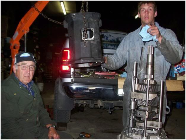
 Once you have that done you can lift the main housing off.  Make sure to watch that shift tower hole, that piece that you punched the pin out of has to be turned just right so it doesn’t catch.  You should now be able to pull the main housing straight off.  Now you get your first full view of all those beautiful gears. Don’t I look happy? (Actually I was trying to tell my other grandpa how to work my camera.)

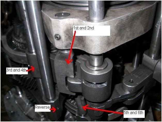
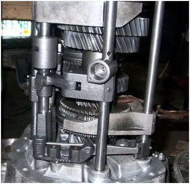
Look at the way the shift forks fit together, I didn’t do this and had to sit and figure that all out on my own.  I put a picture that shows the important area to study.  It actually makes a lot of sense if you sit and figure out how it works.  The forks go in order, 1/2 on the outside 3/4 next followed by 5/6 with reverse on the inside.
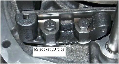
If you’re doing like me and are replacing the 5th gear synchro you don’t have to pull any snap rings or anything, just lift the two shafts out.  Before you can lift them out, you must remove the bolts holding the 5th/6th gear crossover arm.

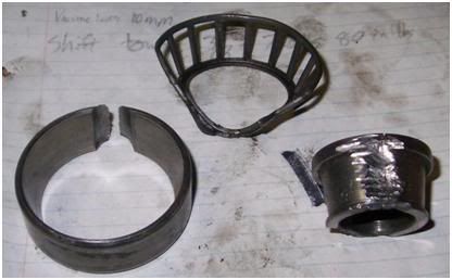
You can now lift the gears out.  You can do this by just screwing a bolt into each of them and lifting them with the engine hoist and a chain.  The one that falls apart is the 5th gear synchro.
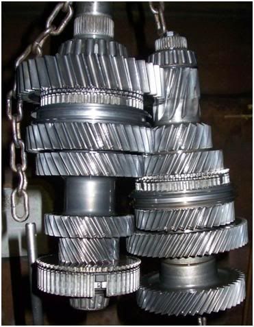
Or if you don’t want that to fall apart just yet can make a clamp to put on there.  I just used two pieces of iron, bent one to make it fit a little better, and drilled a hole for a bolt.

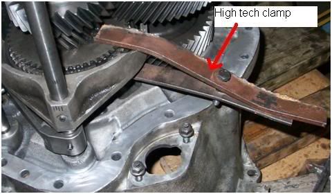
Now you are to the point where you can find and fix your problem area.  Mine was a shot bearing and synchro.


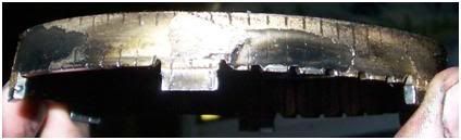
To get the bearing and race out takes a little work.  To get the bearing off I bent the outer ring out and took it off; allowing the rollers to fall out.  Once I had that off I took a cutting wheel and cut a few notches in the part that was still left on the shaft.  I then put one side of the bearing on an anvil and took an air hammer to the other side.  This cracked the bearing and made removal easy. To get the race off I used a die grinder to cut a slit in one side.  Once one side was cut through removal was easy.
 
Save both the bearing and the race until after you have the new ones installed.  I used a press and the old pieces to press the new pieces on.  I used the old pieces because since they were notched or cracked they would slide on and off easy and were exactly the right size to push the new ones on with.
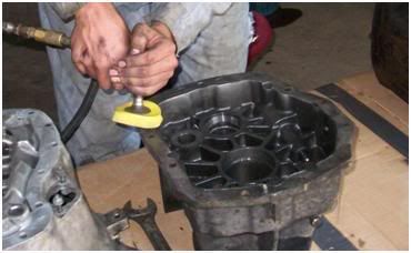
Now that I had the problem fixed it was time to get ready to put everything back together.  First clean everything up. I used a power washer to wash the parts off and then used an air hose to blow everything off.  The power washer removes the grime and such, but the silicon requires a little more work.

Once you have everything cleaned up you can start trying to put it all back together.   The first order of business for me was to put the synchro back together.  It takes a little patience to get all the balls and springs in there but it is doable.  You have to work the outer ring to get it to hold the first 2 in while you are putting in the last one.  The teeth on the piece that isn’t a ball or spring go out to mesh with the teeth on the outer ring.
 
Once you have all the pieces back into the synchro I recommend putting the clamp back on so it can’t fall apart again.
Assembly and installation is the reverse of removal…I wouldn’t do that to you, I hate when manuals say that.
When you are ready to begin putting things back together the first order of business is to clamp the 5th gear synchro back together.  Once you have that clamped back together you can hang the gears again.  Once you have the two sets of gears hanging and aligned you can begin putting the shift rails back on.  Once you have the shift rails back on you can set that whole assembly back into the bell housing.

I waited until after I had it set down to put in the crossover bar for 5th and 6th.  Once you have it set down and are sure all of the shift rails are in the correct place you can put the two bolts for the crossover arm back in.

After you get those tightened you are ready to put the main case back on.  I used the cherry picker to put it back on slowly to make sure nothing was binding.  I set it all the way down to make sure everything would slide together nicely and then lifted it back up to use the case to hold the shift cup at the right height, that way I only had to worry about turning it back and forth to make the hole line up as I put the roll pin back in.

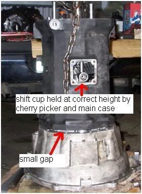
I left the case at this height to put the sealant in.

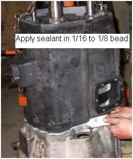
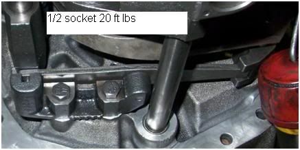
After I got the sealant in there I set the case back down and then proceeded to torque the 5 exterior bolts.  Put a little bit of sealant on any bolts that are going back into anything that has fluid.

Once I had those tightened put the transmission horizontal and proceeded to torque the other bolts.

I double checked all the bolts to make sure they were the correct torque, especially the 5 exterior bolts that were tightened before the rest.
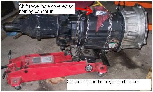
After you are done putting the bell housing back on you can stand it back up.  I plugged all the holes to make sure that no parts could fall in if I accidentally dropped something.

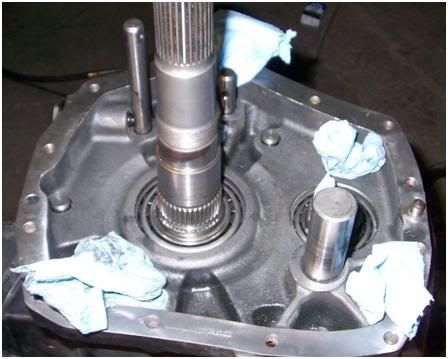
Now that you have the main case tightened down you need to make sure that the tolerances are correct.  I used a dial indicator with a magnetic base to take my measurements.

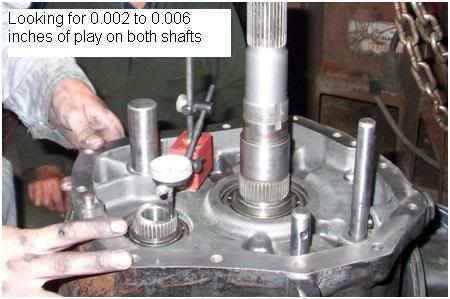
To make the adjustments you can add or remove shims. I used a used a piece of iron and a hammer to tap against the shafts after I made an adjustment to make sure they were tight against the shims.

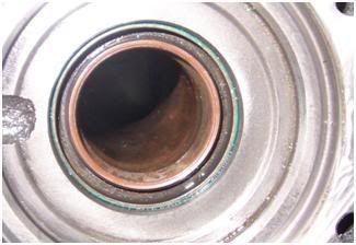
I highly recommend replacing the seals before you put it back together.  You might be able to get away with running the old seals, but the risk just isn’t worth it.  It is at this point that I recommend replacing the seals.  The front seal is in the center cover and the rear seal is in the extension housing.  A large socket works well to tap against to put them back in.

Once you have replaced the seals, or if you have decided you aren’t going to (bad idea), you can seal and torque the center cover back on.
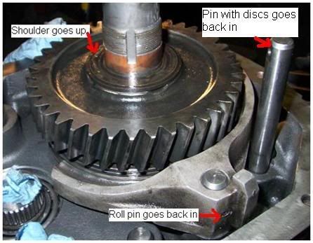
After you have the center cover sealed stand the transmission back up on end and finish assembling the gears that go inside the extension housing.  The synchro and shift fork go first followed by the gear and big washer.  On the washer the side with a shoulder goes towards the bearing.

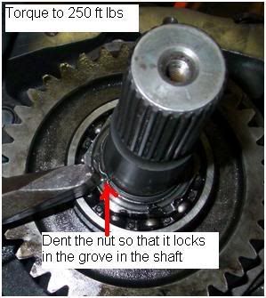
The last thing on this particular shaft is the nut.  Once you get it tight don’t forget to dent it so it can’t back out.  You can also use the chisel to tighten it back up, but it isn’t the approved way to do it. ;)

You can finish putting all the gears back in and check your endplay for the reverse shaft.  To do this you will measure the height of the bearing from the gasket surface and the depth of the race in the extension housing from the gasket surface.  Subtract the second measurement from the first, this is your endplay. 

Once you have your endplay set, you can use the cherry picker to set the adapter housing back on.  I set it all the way down to make sure everything went together easily and then lifted it back up to put the sealer in.  Once you have the sealant in set it back down and torque it.

You can put these two bolts back in at this time, don’t forget the sealant. 

Once I had it all together I put the shift tower on just to make sure it would go through the gears.  After I had checked this and knew I hadn’t dropped anything in the main case I bolted the PTO covers back on.  Make sure you have all the surfaces clean before you start putting sealant on.

You can now put the transfer case back on.  Mine had a gasket on it when I took it apart, but I was told sealant works just fine for when you put it back together.

You are now ready to put it back in the truck.  I found a better transmission jack that would allow me to roll the entire assembly under the truck.

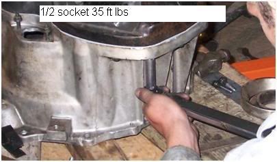
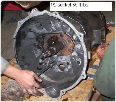
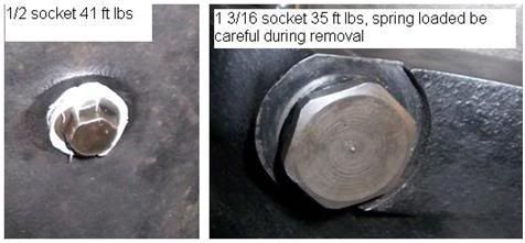
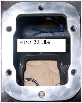
When you get it back under the truck the first order of business is to get it bolted back to the engine.  Do not use the bolts to pull it up to the engine.  I put mine in 6th and locked the transfer case in 4X4 so that I could just turn the disc that the front driveshaft bolts to align the splines for the input shaft and clutch.  Keep the distance even between the sides and top and bottom of the bell housing and clutch.  It should slide together pretty easily if you have everything lined up.  Remember to watch where the shift tower bolts on as that is what is most likely to hit the floor.  Once you get it back together you can put the bolts back in and torque it down.   It is a 14mm socket and the torque is 35 ft lbs.
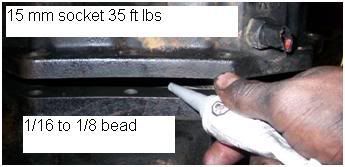
Once you have that back in I would put the support cross member back in.  I used the port a power to spread the frame rails to get it back in.  The heads of the bolts are 13mm and the nuts are 15mm. Set the transmission down onto the cross member and bolt it down (15mm).
After I had the support cross member in and the transmission bolted to the engine I took out the jacks so it was easier to work underneath the truck.  Put the clutch release cylinder ( ½ ), starter ( 12 point 10 mm), transfer case linkage, and vacuum lines (10mm) back in at this point.  For pictures go back to earlier in the document.
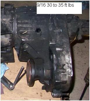
Once you have that stuff connected you are ready to put the driveshafts back in.  When you go to bolt the front driveshaft (5/8) back on make sure you get your alignment marks back in the correct places.  For the rear driveshaft I slid it into the transfer case first and used a jackstand to hold up the back end while I put the hanger bearing back in (15mm socket and wrench).  When you go to bolt the rear U-joint together (5/16) make sure you get it aligned the same way as when you took it out.
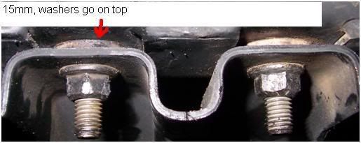
Now put the other cross member and skid plate back in (15mm).  The washers for the cross member go on top of the cross member.

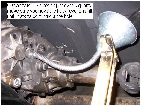
Now that you have everything reassembled underneath the truck you can fill the transfer case and transmission with fluid.  For the transfer case I used a flex funnel pushed all the way against the floor to get the fluid in.  It uses automatic transmission fluid.

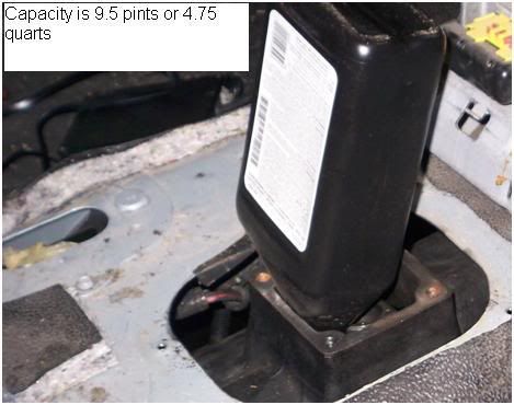
The transmission was much easier as you can use the shift tower hole to fill it.  There is a lot of debate on which fluids are best, I just used the part number off of the PTO cover and got if from the dealer.  I just put in the full 5 quarts as a lot of places say to overfill it by up to a quart.

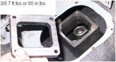
Now that you have the transmission full of fluid you are ready to put the inside back together.  The rubber and metal gasket that was between the shift tower and the transmission gets sealant on the side that goes against the transmission but not the rubber side that is up.  Once you have sealant on that put the shift tower back in and bolt it down.

After you have the shift tower back in finish putting your interior back together.  The dust boot and console use 5/16 and the transfer case shifter uses 10mm.
Now is the moment of truth, start her up and see if you have 6 forward and one reverse.  You should of seen the look on my face when I started mine and everything worked the way it was supposed to.  I hope you get that same look on your face when you start yours for the first time.
I have to thank my grandpa for letting me use his shop and tools.  He also shared a little wisdom every once in a while (like using the chisel to loosen the huge nut on the output shaft or using an air hammer to crack the bearing so it came off easy).  He used to do a lot of trucking and farming and did all his own maintenance so I had more tools than I needed for this job.  That’s also why I had to find a different transmission jack, the one for the semis was too tall to roll out from underneath my truck with the transmission on it.  The project took me a few days, but I didn’t work to fast and had no guidance, hopefully this helps you so it goes quicker and you don’t have to figure to many things out on your own.

'06 2500 CTD Mega auto
'02 2500 CTD QCLB 6 speed
'02 2500 CTD QCLB auto

Offline Kilch123

  • Regular Member
  • Mechanical God!!!
  • *
  • Posts: 10466
  • Thanks Pat and Adam!!!
  • Awards:
    DECEMBER ROTM 2011Mile High500 HPDistinguishedTech CertifiedDonorAir Force
Re: DIY: Transmission work NV5600
« Reply #2 on: April 09, 2009, 02:44:26 pm »
Wow - great write-up  :clap:

Looked like a lot of work there.  How long did it take you?
***Currently at Smokin Okie Diesel - Enid OK***
99 3500QCLB 6x6 5 Speed - D Tech Twins,SB DD3600,Adrenaline/Pulse,Smarty,DDP 110's,Hamilton's,ARP Studs,Airdog,CFE+,Silverline4",Mag-Hytec F/R,Amsoil-B2B,Isspro Performax Boost/EGT & Fuel-pillar mount,2Low Mod,BD SBS and Short Shifter, All LED


516/1127     9/18/09
14.788/93.78  8/8/09

If You Are Not Willing To Stand Behind Our Troops, Please Feel Free To Stand In Front Of Them!

Offline lilfroger

  • Administrator
  • Mechanical God!!!
  • *****
  • Posts: 13251
  • Not a "god" ... I just talk a lot
  • Awards:
    ROTMDonorARMYMOTY
Re: DIY: Transmission work NV5600
« Reply #3 on: April 09, 2009, 03:12:10 pm »
GREAT Write up!!  I will never be trying this :D
Install, Owners, & Service Manuals for many years & makes:
http://www.scribd.com/lilfroger

Offline Cumminalong

  • Master of Destruction - Breaker of performance parts
  • Official DOF Vendor
  • Mechanical God!!!
  • ***
  • Posts: 25349
  • The BOMB'r
  • Awards:
    1100ROTYMember of the Year1 Tech
Re: DIY: Transmission work NV5600
« Reply #4 on: April 09, 2009, 09:08:12 pm »
 :eek:

Holy Crap!

That was one HELLUVA write-up!

Offline noplugs

  • Kung Fu Panda! - closeted conservative
  • Administrator
  • NASCAR Crew Chief
  • *****
  • Posts: 7684
  • This thing has 4 wheel drive?
  • Awards:
    600 HPShade TreeDistinguishedApril ROTMDonor
Re: DIY: Transmission work NV5600
« Reply #5 on: April 09, 2009, 09:22:38 pm »
WOW!. Thats nice work. Super write-up too.
659 HP/1287 TQ -- She's BACK!  Yeah,,, nope she's not stock..

Doghouse Diesel Performance rocks

Nothing is exactly as it seems,nor is it otherwise

Offline mayfair

  • Master Smartazz!!!
  • Shade Tree Certified
  • Mechanical God!!!
  • ***
  • Posts: 19914
  • Last 8 - w j 1 8 7 6 2 5
  • Awards:
    rotm200k400 HPShade TreeContributorDonor
Re: DIY: Transmission work NV5600
« Reply #6 on: April 09, 2009, 10:17:24 pm »
Dude you're a MADMAN !!! :eek:

I would have NEVER attempted something like this, especially by myself. You've got some MAD skilz fo sho !!

I've got one question though ...

Is it because you FINALLY slipped a ring on her hand that the Mrs. no longer helps with these truck projects.?

:43:

AWESOME write up !! :punk:

Thank You for taking the time !! :up:

Offline R0oster31

  • Tech Certified
  • Master Technician
  • *****
  • Posts: 1514
  • Awards:
    DonorROTMTech Certified500HPAF
Re: DIY: Transmission work NV5600
« Reply #7 on: April 10, 2009, 12:21:44 am »
Actually Mayfair this was from before we were married, she was in CO and I did this in MN.  I had posted it over on the other forum just about 2 years ago now and was reading a few of the other DIYs here and realized, hey I should move this over, luckily I still had it saved on my computer so I didn't have to go to the other forum. 

As far as time it took me about a week to do this, but I was at my grandparents and we would put in a half day go fishing or just go fishing the whole day while we waited for parts (I didn't know the bearing was bad prior to getting it apart).  It was a really relaxed pace (I had 60 days off between commissioning and having to be at my first base) and in actuality it took us about three days of actual work.  If I had all the parts I could get it done in one day with someone helping me, it would be a long day but you could do it in one.

'06 2500 CTD Mega auto
'02 2500 CTD QCLB 6 speed
'02 2500 CTD QCLB auto

Offline mayfair

  • Master Smartazz!!!
  • Shade Tree Certified
  • Mechanical God!!!
  • ***
  • Posts: 19914
  • Last 8 - w j 1 8 7 6 2 5
  • Awards:
    rotm200k400 HPShade TreeContributorDonor
Re: DIY: Transmission work NV5600
« Reply #8 on: April 10, 2009, 05:01:27 pm »
LOL ... I like the part where you say " If you look at it, it really makes sense"

:scratch:

I'm LAUGHING MY AZZ off because all I see is a rubics cube staring me in the face

:lol:

Offline NickBeek

  • Regular Member
  • Mechanical God!!!
  • *
  • Posts: 11220
  • Awards:
    Donor150k400 HPContributor
Re: DIY: Transmission work NV5600
« Reply #9 on: September 23, 2009, 02:28:38 am »
Excellent write up! :up:

I can't believe they let you FLY planes. Usually guys with that much mechanical expertise don't get anywhere near the controls..... :lol:
2014 Ram 2500 Laramie, 4x4, 3.42 gears. Auto Trans, Crew cab, long bed. Window Visors, trifold bed cover.


Offline R0oster31

  • Tech Certified
  • Master Technician
  • *****
  • Posts: 1514
  • Awards:
    DonorROTMTech Certified500HPAF
Re: DIY: Transmission work NV5600
« Reply #10 on: October 24, 2009, 08:14:46 am »
What they don't know won't hurt them.

'06 2500 CTD Mega auto
'02 2500 CTD QCLB 6 speed
'02 2500 CTD QCLB auto


Questions, Concerns, Comments? Contact DOF Administrators
DodgeOwnerForums.com is not affiliated with Chrysler Group, LLC or Cummins, Inc